
|
|
|||||||
| FM/DM threads Everything about FM/DM in CoD |
 |
|
|
Thread Tools | Display Modes |
|
#1
 01-12-2012, 11:25 AM
|
|||
|
|||
|
There has been some discussion lately on the Merlin boost control/cutout, and whether or not it works correctly in Cliffs of Dover. However the other thread has drifted to the discussion of whether or not 100 octane is modeled/should be modeled/ was available etc. SpitMkI/II and over boost
I have a background in control engineering and my interest is: how did the real boost control and override work exactly? What is being measured, what is being manipulated and how? In modern process control, we have sensors (measuring the process), actuators (intervening in the process), and computer logic driven control loops feeding electrical information between the two. I am fascinated with 1940s and earlier control engineering, where to control a parameter like actual boost at a rated boost setpoint the control loop is a purely mechanical system where the sensors, actuator and control logic are real interconnected parts like valves, pistons and control linkages. The reason for boost regulation in the Merlin is pretty clear; the supercharger in early models was capable of outputting around 20 psi on the ground, whereas a suitable limit (for initial 87 octane fuel) was 6.25 psi. Higher boost (and hence compression) gives extra power and puts extra stress on the engine, but the real problem is that above a boost threshold (determined by fuel octane) predetonation of fuel-air will occur, power will be lost and wear will greatly accelerate even if the motor does not fail catastrophically. A common explanation (various forum posts) for the boost regulation in early Merlins is a simple pressure regulator that vents excess boost pressure to the atmosphere. In fact the A2A simulations company (who are very serious about simulation accuracy for their FSX add-in aircraft and produce fantastic products) claim (at least initially) this is correct for their Spitfire I/II in the following thread (and some others not linked): http://www.a2asimulations.com/forum/...p?f=77&t=27554 However, in the face of persistent questions they seem to have backtracked by the end, although it is a bit unclear! The problem with venting excess pressure for boost control is fairly clear. It appears that the Merlin follows a conventional supercharger layout in that the supercharger compresses not air alone, but fuel-air from the carburetor output. It seems very unlikely that a system that vents fuel-air (in fact the majority of it by volume) would be considered by the original engineers due to the resulting problems in fuel economy and safety. Instead the supercharger input must be throttled to reduce boost, i.e. by the main throttle in the carburetor (which is upstream from the supercharger) The best explanation for a suitable boost control I came across was this document: Rolls-Royce Merlin Automatic Boost Regulator, Courtesy of Dave Birch and the Rolls-Royce Heritage Trust It appears to (but I can't confirm it to be) a period document with the text re-input and scans of the original diagrams. Unfortunately there is no date and a passing reference to the Merlin III, so assessing it’s relevance is a bit difficult. However this system or one like it seems the best candidate as it does not involve routine venting of fuel-air for boost pressure control. It refers to a system where rated boost is +9psi and override boost is +12psi (i.e. 100 octane conversion for early Spitfire). I recommend a full read of the document if interested, but here is a simplified version of the system with some of the detail stripped away (Figure 1). Basically the boost cylinder valve is plumbed so that a relatively high pressure (from the supercharger output itself) is routed to one side or the other of a piston attached to the throttle via linkage. When actual boost is equal to rated (desired) boost, both sides of the cylinder are sealed and the piston stays where it is. There is more detail about how this is actually done in the original document. The piston has a linkage which alters the mechanical relationship between the pilot's throttle lever and actual throttle plate. Figure 1 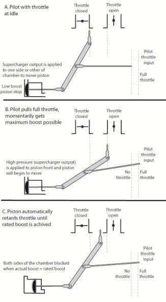 The system is very simple and elegant. Basically if the pilot adds more throttle than gives the rated (maximum) boost level, the valve piston brings the actual throttle plate setting back to an intermediate value, thus modifying the pilot’s input and effectively taking throttle control away from him. If the pilot whacks the throttle forward he will momentarily get full throttle and boost, until the piston manages to get the real throttle position back to whatever level gives rated boost (with oscillations, this being a mechanical system). With a system like this, you could imagine taking actual throttle control away from the pilot totally, and giving a ‘throttle’ lever with only three positions effectively corresponding to: 1. Idle 2. As much boost as possible up to rated boost 3. As much boost as possible (over boost) Which might be OK for combat but rather painful for cruise. The system above is actually much better in this regard, the pilot gets direct throttle control as long as he or she (don’t forget the Air Transport Auxiliary!) doesn’t ask for above rated boost. My reading of the system is that although it will not control at under the rated boost, it will provide some dampening which could be construed at partial control. For instance if the pilot selects +2psi boost (< rated boost) and climbs, the system will not keep +2psi as the outside pressure drops but in general will not fall off as fast as it would if the system was not there (i.e. some degree of automatic throttle manipulation occurs). Overboost The system gives two different ways to overboost the engine. 1) Hole method. Controlled leaks (e.g. holes) can be added in the plumbing around the valve/piston that effectively add a pressure increment to the boost setpoint, i.e. going from rated boost to an overboost set at the designer’s discretion. These holes can be covered/uncovered based on a pilot cable control (the boost cut out). 2) Gate method. Add an extra physical throttle increment. The boost control piston is designed to be toward the high pressure stop when controlling and the extra throttle pulls greater boost than the system can handle. The piston goes right to the high pressure stop but cannot reverse the pilot’s input (Figure 2). Essentially this override gives a maximum throttle position and consequently whatever boost this represents (this max throttle position could be set to give a particular boost for a specific rpm and ambient pressure condition). Figure 2 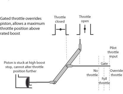 The gate method as described in the document seems a little problematic in what would happen if you were through the gate and went up to sufficient altitude that maximum possible boost fell below rated boost. Either the valve piston would have to pull the throttle back out of the gate (surprising the pilot!), or the linkages would bend/break. However the schematic given for the mechanism is very simple anyway, the real system would likely be somewhat more complicated. Reading the two overboost methods I thought that perhaps the Hurricane used the hole + cable method (i.e. “pull the tit” on the panel) while the Spitfire used the gate method, as when you hit the red overboost lever in the CLoD Spitfire you rotate a cam and make available an extra throttle section. But the A2A Spitfire MKI/II have a red lever but no cam and no extra throttle travel. The A2A people state that the red lever goes to a cable that covers/uncovers holes in the system (as supported by their own research). Just to make things more complicated, the A2A Spitfire MkII also has a gate marked “rated boost” (at gate) and “takeoff boost” (past gate) in addition to the red lever. The pilot notes for the real life Spitfire MkII also show a gate http://www.zenoswarbirdvideos.com/Im...pit2Manual.pdf. I can’t find any material/pictures/diagrams that fit with the concept of the CLoD red lever + cam throttle gate. Instead it appears likely to me that the actual Spitfire Mk I/II used the hole method as described above, with the red lever going to a cable that uncovered the holes in the boost control valve. Origin of overboost Although lacking good references, it is often stated that the boost cutout originally was not intended as an emergency power increase but instead a backup for failure of the boost controller in a minimum boost state and this seems plausible. It is stated that before the modified boost cutout (which turned the boost cut out into a combat boost system for 100 octane), the system allowed boost to 17 psi at full throttle, which is close to the full unthrottled supercharger output at ground level http://www.spitfireperformance.com/spit1-12lbs.jpg. A pilot with full access to 17psi boost at ground level would have to be very careful with his throttle not to exceed the maximum boost for his fuel octane (whatever it was), otherwise the resulting predetonation would rapidly drop the power and damage the engine. However with the boost cutout activated a careful pilot could explore whether he could get a little more than the rated boost (and power) without causing rapid engine failure, and this seems likely to have occurred. It made sense to then modify the boost cutout with extra holes that limited the maximum boost with the cutout activated to an agreed value that gave extra power without destroying the engine in the air (i.e. +12psi for 100 octane fuel), and then allow pilots to use it briefly in combat. Summary Although well sourced information is surprisingly scant, it seems likely the boost regulator in early Spits/Hurricanes was a piston/linkage based system that took over the throttle when boost exceeded the rated amount. The boost cutout was a cable system attached to the red lever (in Spitfires) and nipple like appendage (Hurricanes) that covered/uncovered precise diameter passages or holes in the boost control valve, and not a throttle gate as in CLoD Spitfires (although the real MkII also had a throttle gate that did not require the red lever to access). It was modified with the onset of 100 octane fuel to be a war emergency power device that gave a higher but not maximum boost. If anyone has good information that add to (or totally contradict!) this version of the boost regulator, I would be very interested. What would be great are engineering drawings of actual boost regulators on early or any Merlins, as long as it was clear at what point of the system the boost regulator was actually located. 
|
|
#2
01-12-2012, 12:02 PM
|
|||
|
|||
|
Have you ever tried emailing the folks over at http://fighter-collection.com maybe one of their mechanics could tell you? I'd be interested to know also.
|
|
#3
01-12-2012, 12:22 PM
|
||||
|
||||
|
Superb post, Camber!
Various combat reports definitely confirm your summary and the version with the holes is certainly correct (opposite to the throttle gate we've got in Clod - that's a late mark thing, e.g. Mk.IX Spitfire with the gate that could be attached both ways in order to restrict or allow the extra movement of the throttle lever regarding to the fuel used etc). Exact locations of these holes and their diameter are both well researched and documented. Unfortunately, I am far from being an expert and I don't remember where exactly I've seen the diagram with complete cut-outs. But it was certainly not the fuel / air venting (that would be disastrous!) but just the air on the way from the supercharger to the valves, that has been sucked out. I believe these holes have been drilled into original Boost cut-out valves. I will have a look in the ''Merlin in perspective - the combat years'' publication later on and I will post anything relevant when I come across it. As you say, the A2A guys seem to have done great deal of research and their FSX product is extremely close to the real thing (although there are some details or say grey areas as with Mk.IIa for example, but fair enough). And the way they portrayed the red gate seems to be spot on. The only problem there is that when you move the red gate, you need to move the throttle back and forth to achieve that extra MFP. This is due to FSX engine limitations and I remember reading that in the real Spitfire, you only moved the gate, there was no extra throttle movement - sort of like pulling the plug in a CLoD Hurricane. I find it rather unlikely that a Hurricane would use different method od BCC-O than the Spitfire. Everything you wrote in your summary seems to be correct, including drilling the extra holes in order to get safe-sh +12 rather than +16/+17PSI from a Merlin III / XII. This is also quite well docummented including some tests done at Rolls-Royce (BCC-O being backup for failure first and then used as WEP option etc.) It would be interesting to see if this air suction (with BCC-O activated) had any impact at the mixture richness at all...
__________________
Bobika. Last edited by Robo.; 01-13-2012 at 08:48 AM. Reason: typing
|
|
#6
01-12-2012, 04:16 PM
|
|||
|
|||
|
Injected you said ?
No seriously what afraid me the most is that duct full of boosted mixture right near the pilot arm and leg beyond the (relative) protection of the firewall. I understand better now why the fire hazard was greater inside a Hurri/Spit than on the 109. Conjecturing : won't it be a valid point to change the boost ctrl design from holes to valves ?
|
|
#7
01-12-2012, 09:46 PM
|
|||
|
|||
|
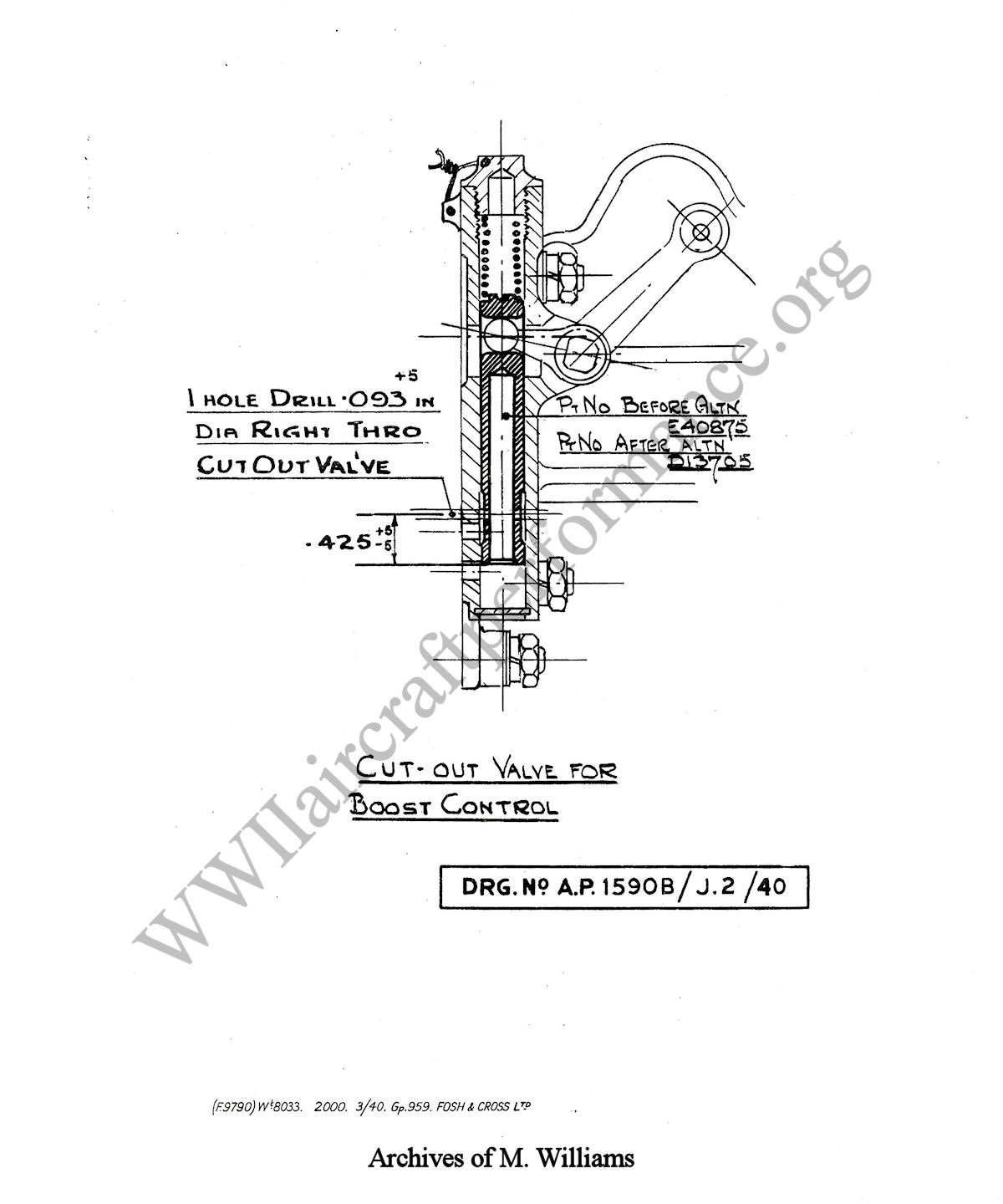
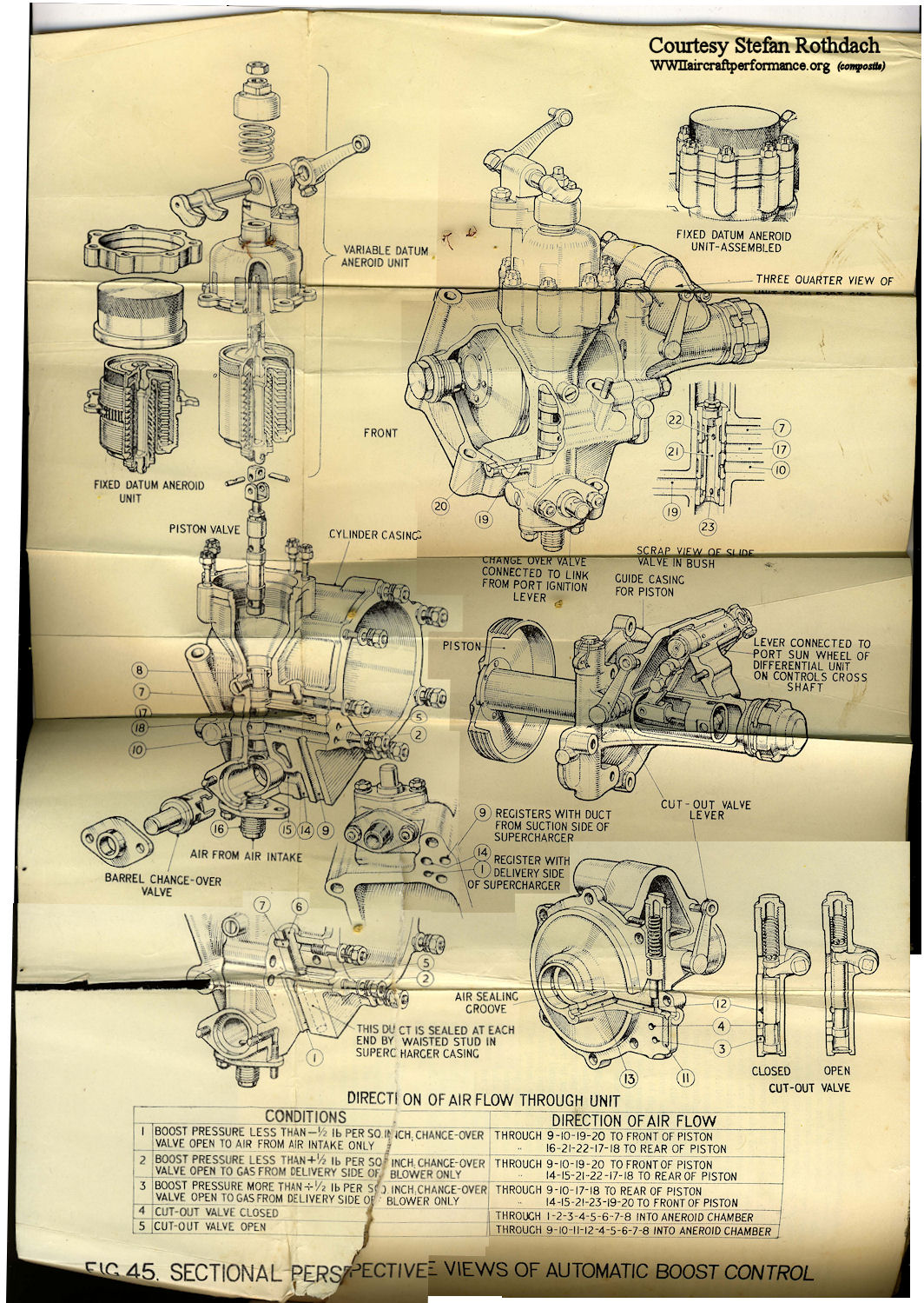
Lane; thank you very much! That is EXACTLY what I wanted!
From a quick look it is consistent with the Rolls Royce Heritage trust document but with the actual structure and plumbing. The second diagram appears to show the whole thing pre-hole and the first where to drill the hole. Fantastic! I will take a good look at it all however and work out if I need to edit the original post. At first glance it appears that pre hole, the "leak" is introduced from the pressure to the supply side of the supercharger thus maintaining a closed system. With hole it appears there is a possibility of fuel-air venting to atmosphere when you are using combat +12psi boost.
|
|
#8
01-12-2012, 11:40 PM
|
|||
|
|||
|
The text pages from AP 1590B Merlin II and III Aero-Engines about Automatic Boost Control. The drawing has already been posted.
|
|
#9
01-12-2012, 11:43 PM
|
|||
|
|||
|
Continued
|
|
#10
01-12-2012, 11:49 PM
|
|||
|
|||
|
And the last page.
|
|
| Thread Tools | |
| Display Modes | |
|
|


 Linear Mode

